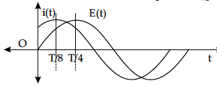
The figure shows two sinusoidal curves representing oscillating supply voltage and current in an ac circuit.

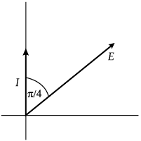
Draw a phasor diagram to represent the current and supply voltage appropriately as phasors. State the phase difference between the two quantities.

Draw a phasor diagram to represent the current and supply voltage appropriately as phasors. State the phase difference between the two quantities.


Show that in the free oscillations of an LC circuit, the sum of energies stored in the capacitor and the inductor is constant in time.
A source of ac voltage V = V₀ sin ωt, is connected across a pure inductor of inductance L. Derive the expressions for the instantaneous current in the circuit. Show that average power dissipated in the circuit is zero.
The figure shows a series LCR circuit connected to a variable frequency of 200 V source with L = 50 mH, C = 80 µF and R = 40 Ω find.
(i) the source frequency which drives the circuit in resonance;
(ii) the quality factor (Q) of the circuit.
In a series LCR circuit, obtain the conditions under which
(i) the impedance of the circuit is minimum, and
(ii) wattless current flows in the circuit.
In highly inductive load circuit, it is more dangerous when
(a) we close the switch
(b) open the switch
(c) increasing the resistance
(d) decreasing the resistance
A lamp is connected in series with a capacitor. Predict your observation for dc and ac connections. What happens in each if the capacitance of the capacitor is reduced ?
An ac voltage V = V₀ sin ωt is applied to a pure inductor L. Obtain an expression for the current in the circuit. Prove that the average power supplied to an inductor over one complete cycle is zero.
Two point charges q1 and q2 are located at and respectively in an external electric field E. Obtain the expression for the total work done in assembling this configuration.
A network of resistors is connected to a 16 V battery with internal resistance of 1 Ω, as shown in the following figure. Compute the equivalent resistance of the network.
A particle of mass 10⁻³ kg and charge 5 mC enters into a uniform electric field of 2×10⁵ NC⁻¹, moving with a velocity of 20 ms⁻¹ in a direction opposite to that of the field. Calculate the distance it would travel before coming to rest.
Two metallic wires P₁ and P₂ of the same material and same length but different cross-sectional areas A₁ and A₂ are joined together and then connected to a source of emf. Find the ratio of the drift velocities of free electrons in the wires P₁ and P₂ if the wires are connected
(i) in series, and (ii) in parallel.
An electric dipole of length 4 cm, when placed with its axis making an angle of 60° with a uniform electric field, experiences a torque of Nm. Calculate the potential energy of the dipole, if it has charge ± 8 nC.
The figure shows two sinusoidal curves representing oscillating supply voltage and current in an ac circuit.
Two cells of E.M.F. 10 V and 2 V and internal resistances 10 Ω and 5 Ω respectively, are connected in parallel as shown. Find the effective voltage across R.
