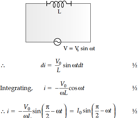
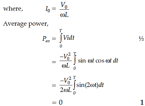
A source of ac voltage V = V₀ sin ωt, is connected across a pure inductor of inductance L. Derive the expressions for the instantaneous current in the circuit. Show that average power dissipated in the circuit is zero.


An ac voltage V = V₀ sin ωt is applied to a pure inductor L. Obtain an expression for the current in the circuit. Prove that the average power supplied to an inductor over one complete cycle is zero.
An alternating voltage given by V = 140sin314 t is connected across a pure resistor of 50 Find :
(i) the frequency of the source.
(ii) the rms current through the resistor.
A source of ac voltage V = V₀ sin ωt is connected to a series combination of a resistor ‘R’ and a capacitor ‘C’. Draw the phasor diagram and use it to obtain the expression for
(i) impedance of the circuit and
(ii) phase angle.
A 40 mF capacitor is connected to a 200 V, 50 Hz ac supply. The r.m.s value of the current in the circuit is, nearly
(a) 1.7 A
(b) 2.05 A
(c) 2.5 A
(d) 25.1 A
Show that in the free oscillations of an LC circuit, the sum of energies stored in the capacitor and the inductor is constant in time.
For an ideal conductor, connected across a sinusoidal ac voltage source. State which one of the following quantity is zero :
(i) Instantaneous power
(ii) Average power over full cycle of the ac voltage source.
In a series LCR circuit, obtain the conditions under which
(i) the impedance of the circuit is minimum, and
(ii) wattless current flows in the circuit.
An inductor L of inductance is connected in series with a bulb B and an ac source. How would brightness of the bulb change when
(i) number of turns in the inductor is reduced,
(ii) an iron rod is inserted in the inductor and
(iii) a capacitor of reactance is inserted in series in the circuit. Justify your answer in each case.
A voltage V = V₀ sin ωt is applied to a series LCR circuit. Derive the expression for the average power dissipate over a cycle.Under what conditions is
(i) no power dissipated even though the current flows through the circuit,
(ii)maximum power dissipated in the circuit ?
(i) Find the value of the phase difference between the current and the voltage in the series LCR circuit shown below. Which one leads in phase : current or voltage ?
(ii) Without making any other change, find the value of the additional capacitor C₁, to be connected in parallel with the capacitor C, in order to make the power factor of the circuit unity.
The figure shows a series LCR circuit with L = 5.0 H, C = 80 µF, R = 40 Ω connected to a variable frequency of 240 V source. Calculate
What is relaxation time ? Derive an expression for resistivity of a wire in terms of number density of free electrons and relaxation time.
A cell of emf ‘E’ and internal resistance ‘r’ is connected across a variable load resistor R. Draw the plots of the terminal voltage V versus (i) R and
(ii) the current I.
It is found that when R = 4 Ω, the current is 1 A when R is increased to 9 Ω, the current reduces to 0.5 A. Find the values of the emf E and internal resistance r.
Two point charges + q and –2q are placed at the vertices ‘B’ and ‘C’ of an equilateral triangle ABC of side ‘a‘ as given in the figure. Obtain the expression for (i) the magnitude and (ii) the direction of the resultant electric field at the vertex A due to these two charges.
