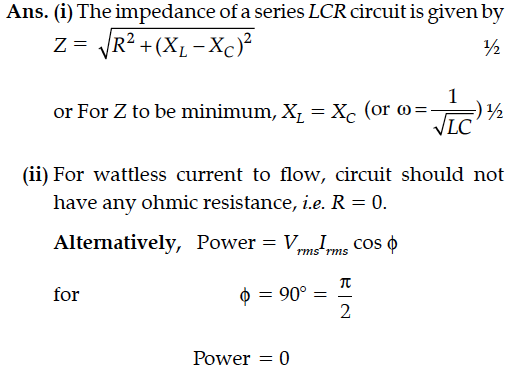
In a series LCR circuit, obtain the conditions under which
(i) the impedance of the circuit is minimum, and
(ii) wattless current flows in the circuit.
(i) the impedance of the circuit is minimum, and
(ii) wattless current flows in the circuit.


In series R-L-C circuit, quality factor can be improved by
(a) decreasing L
(b) increasing C
(c) decreasing R
(d) decreasing R & L
Obtain the expression for the energy density of magnitude field B produced in the inductor.
Show that the current leads the voltage in phase by in an ac circuit containing an ideal capacitor.
Show that in the free oscillations of an LC circuit, the sum of energies stored in the capacitor and the inductor is constant in time.
In highly inductive load circuit, it is more dangerous when
(a) we close the switch
(b) open the switch
(c) increasing the resistance
(d) decreasing the resistance
In an A.C. circuit, Irms and I₀ are related as
(a) Irms = p I₀
(b) Irms = 2 I₀
(c) Irms = I₀/p
(d) Irms =I₀ / 2
A cell of emf E and internal resistance r is connected to two external resistances R₁ and R₂ and a perfect ammeter. The current in the circuit is measured in four different situations :
(i) without any external resistance in the circuit
(ii) with resistance R1 only
(iii) with R1 and R2 in series combination
(iv) with R1 and R2 in parallel combination.
The currents measured in the four cases are 0.42 A, 1.05 A, 1.4 A and 4.2 A, but not necessarily in that order. Identify the currents corresponding to the four cases mentioned above.
In a series LCR circuit, obtain the conditions under which
(i) the impedance of the circuit is minimum, and
(ii) wattless current flows in the circuit.
Find the expression for electric field intensity in an axial position due to electric dipole.
Two cells of E.M.F. 10 V and 2 V and internal resistances 10 Ω and 5 Ω respectively, are connected in parallel as shown. Find the effective voltage across R.
Find the P.E. associated with a charge q if it were present at the point P with respect to the ‘setup’ of two charged spheres, arranged as shown. Here O is the mid-point of the line O1O2.
The figure shows two sinusoidal curves representing oscillating supply voltage and current in an ac circuit.
A cell of emf 4 V and internal resistance 1 W is connected to a d.c. source of 10 V through a resistor of 5 W. Calculate the terminal voltage across the cell during charging.
