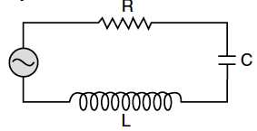
The figure shows a series LCR circuit with L = 5.0 H, C = 80 µF, R = 40 Ω connected to a variable frequency of 240 V source. Calculate

(i) The angular frequency of the source which drives the circuit at resonance.
(ii) The current at the resonating frequency.
(iii) The rms potential drop across the capacitor at resonance.

(i) The angular frequency of the source which drives the circuit at resonance.
(ii) The current at the resonating frequency.
(iii) The rms potential drop across the capacitor at resonance.

The figure shows a series LCR circuit connected to a variable frequency of 200 V source with L = 50 mH, C = 80 µF and R = 40 Ω find.
(i) the source frequency which drives the circuit in resonance;
(ii) the quality factor (Q) of the circuit.
An inductor of 200 mH, capacitor of 400 µF and a resistor of 10 Ω are connected in series to ac source of 50 V of variable frequency. Calculate the
(a) angular frequency at which maximum power dissipation occurs in the circuit and the corresponding value of the effective current, and
(b) value of Q-factor in the circuit.
An alternating voltage given by V = 140sin314 t is connected across a pure resistor of 50 Find :
(i) the frequency of the source.
(ii) the rms current through the resistor.
A source of ac voltage V = V₀ sin ωt, is connected across a pure inductor of inductance L. Derive the expressions for the instantaneous current in the circuit. Show that average power dissipated in the circuit is zero.
In a series LCR circuit, obtain the conditions under which
(i) the impedance of the circuit is minimum, and
(ii) wattless current flows in the circuit.
For an ideal conductor, connected across a sinusoidal ac voltage source. State which one of the following quantity is zero :
(i) Instantaneous power
(ii) Average power over full cycle of the ac voltage source.
A circuit containing an 80 mH inductor and a 250 µF capacitor in series connected to a 240 V,100 rad/s supply. The resistance of the circuit is negligible.
(i) Obtain rms value of current.
(ii) What is the total average power consumed by the circuit ?
A student connects a cell, of emf E2 and internal resistance r2 with a cell of emf E1 and internal resistance r1, such that their combination has a net internal resistance less than r1. This combination is then connected across a resistance R. Draw a diagram of the 'set-up' and obtain an expression for the current flowing through the resistance.
A circuit containing an 80 mH inductor and a 250 µF capacitor in series connected to a 240 V,100 rad/s supply. The resistance of the circuit is negligible.
(i) Obtain rms value of current.
(ii) What is the total average power consumed by the circuit ?
The figure shows a series LCR circuit with L = 5.0 H, C = 80 µF, R = 40 Ω connected to a variable frequency of 240 V source. Calculate
Two material bars A and B of equal area of crosssection, are connected in series to a DC supply. A is made of usual resistance wire and B of an n-type semiconductor.
(i) In which bar is drift speed of free electrons greater?
(ii) If the same constant current continues to flow for a long time, how will the voltage drop across A and B be affected?
Justify each error.
Derive an expression for electric field of a dipole at a point on the equatorial plane of the dipole. How does the field vary at large distances?
(i) Derive the expression for the electric potential due to an electric dipole at a point on its axial line.
(ii) Depict the equipotential surface due to electric dipole.
A voltage V = V₀ sin ωt is applied to a series LCR circuit. Derive the expression for the average power dissipate over a cycle.Under what conditions is
(i) no power dissipated even though the current flows through the circuit,
(ii)maximum power dissipated in the circuit ?
