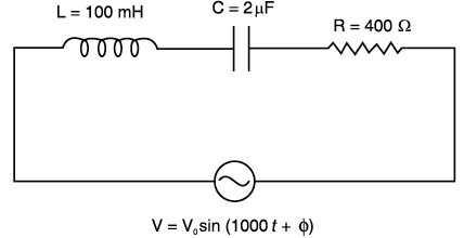
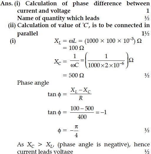
(i) Find the value of the phase difference between the current and the voltage in the series LCR circuit shown below. Which one leads in phase : current or voltage ?
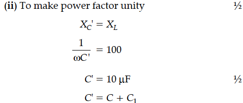
(ii) Without making any other change, find the value of the additional capacitor C₁, to be connected in parallel with the capacitor C, in order to make the power factor of the circuit unity.

(ii) Without making any other change, find the value of the additional capacitor C₁, to be connected in parallel with the capacitor C, in order to make the power factor of the circuit unity.


A sinusoidal voltage of peak value 10 V is applied to a series LCR circuit in which resistance,capacitance and inductance have values of 10 Ω,1 µF and 1 H respectively. Find
(i) the peak voltage across the inductor at resonance
(ii) quality factor of the circuit.
The figure shows a series LCR circuit connected to a variable frequency of 200 V source with L = 50 mH, C = 80 µF and R = 40 Ω find.
(i) the source frequency which drives the circuit in resonance;
(ii) the quality factor (Q) of the circuit.
In the following circuit, calculate (i) the capacitance of the capacitor, if the power factor of the circuit is unity, (ii) the Q-factor of this circuit. What is the significance of the Q-factor in ac circuit ? Given the angular frequency of the ac source to be 100rad/s. Calculate the average power dissipated in the circuit.
A voltage V = V₀ sin ωt is applied to a series LCR circuit. Derive the expression for the average power dissipate over a cycle.Under what conditions is
(i) no power dissipated even though the current flows through the circuit,
(ii)maximum power dissipated in the circuit ?
A source of ac voltage V = V₀ sin ωt, is connected across a pure inductor of inductance L. Derive the expressions for the instantaneous current in the circuit. Show that average power dissipated in the circuit is zero.
Derive the expression for the average power dissipated in a series LCR circuit for an ac source of a voltage, V = sin ωt , carrying a current,i = sin (ωt + Φ)
Hence define the term “Wattless current”. State under what condition it can be realized in a circuit.
An ac voltage V = V₀ sin ωt is applied to a pure inductor L. Obtain an expression for the current in the circuit. Prove that the average power supplied to an inductor over one complete cycle is zero.
The temperature coefficient of resistivity, for two materials A and B, are 0.0031 / °C and 0.0068 / °C respectively.
Two resistors R1 and R2, made from materials A and B, respectively, have resistances of 200 Ω and 100 Ω at 0°C. Show on a diagram, the 'colour code', of a carbon resistor, that would have a resistance
equal to the series combination of R1 and R2, at a temperature of 100°C.
(Neglect the ring corresponding to the tolerance of the carbon resistor).
An inductor of 200 mH, capacitor of 400 µF and a resistor of 10 Ω are connected in series to ac source of 50 V of variable frequency. Calculate the
(a) angular frequency at which maximum power dissipation occurs in the circuit and the corresponding value of the effective current, and
(b) value of Q-factor in the circuit.
A charge + Q, is uniformly distributed within a sphere of radius R. Find the electric field, due to this charge distribution, at a distant point r from the centre of the sphere where :
(i) 0 < r < R
(ii) r > R
Define the term current density of a metallic conductor. Deduce the relation connecting current density (J) and the conductivity σ of the conductor, when an electric field E, is applied to it.
Define relaxation time of the free electrons drifting in a conductor. How is it related to the drift velocity of free electrons ? Use this relation to deduce the expression for the electrical resistivity of the material.
First a set of n equal resistors of R each is connected in series to a battery of emf E and internal resistance R. A current I is observed to flow. Then the n resistors are connected in parallel to the same battery. It is observed that the current becomes 10 times. What is n ?
The following table gives the length of three copper wires, their diameters, and the applied potential difference across their ends. Arrange the wires in increasing order according to the following :
(i) The magnitude of the electric field within them,
(ii) The drift speed of electrons through them, and
(iii) The current density within them.
