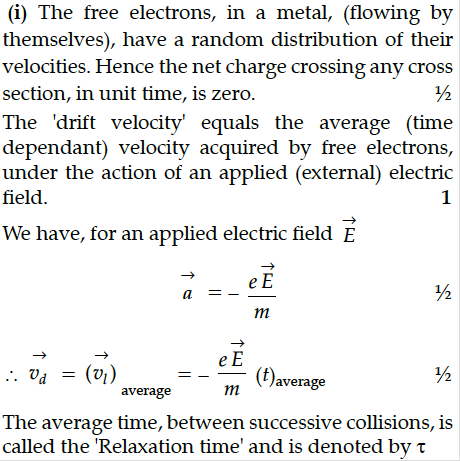
(i) Why do the 'free electrons', in a metal wire, 'flowing by themselves', not cause any current flow in the wire ?
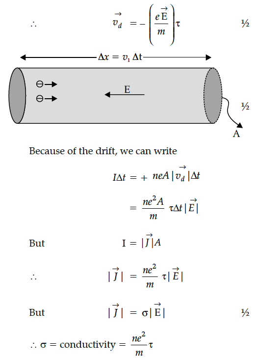
Define 'drift velocity' and obtain an expression for the current flowing in a wire, in terms of the 'drift velocity' of the free electrons.
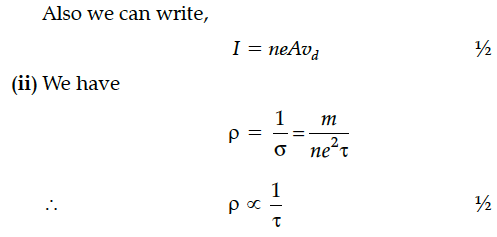
(ii) Use the above expression to show that the 'resistivity', of the material of a wire, is inversely proportional to the 'relaxation time' for the 'free electrons' in the metal.


Define relaxation time of the free electrons drifting in a conductor. How is it related to the drift velocity of free electrons ? Use this relation to deduce the expression for the electrical resistivity of the material.
(a) Define the term ‘conductivity’ of a metallic wire. Write its SI unit.
(b) Using the concept of free electrons in a conductor, derive the expression for the conductivity of a wire in terms of number density and relaxation time. Hence obtain the relation between current density and the applied electric field E.
Derive the expression for the current density of a conductor in terms of the conductivity and applied electric field. Explain, with reason how the mobility of electrons in a conductor changes when the potential difference applied is doubled, keeping the temperature of the conductor constant.
Two metallic wires P₁ and P₂ of the same material and same length but different cross-sectional areas A₁ and A₂ are joined together and then connected to a source of emf. Find the ratio of the drift velocities of free electrons in the wires P₁ and P₂ if the wires are connected
(i) in series, and (ii) in parallel.
(i) Deduce the relation between current I flowing through a conductor and drift velocity of the electrons.
(ii) Figure shows a plot of current ‘I’ flowing through the cross-section of a wire versus the time ‘t’. Use the plot to find the charge flowing in 10 s through the wire.
First a set of n equal resistors of R each is connected in series to a battery of emf E and internal resistance R. A current I is observed to flow. Then the n resistors are connected in parallel to the same battery. It is observed that the current becomes 10 times. What is n ?
A student connects a cell, of emf E2 and internal resistance r2 with a cell of emf E1 and internal resistance r1, such that their combination has a net internal resistance less than r1. This combination is then connected across a resistance R. Draw a diagram of the 'set-up' and obtain an expression for the current flowing through the resistance.
Two point charges q and –q are located at points (0, 0, – a) and (0, 0, a) respectively.
(i) Find the electrostatic potential at (0, 0, z) and (x, y, 0).
(ii) How much work is done in moving a small test charge from the point (5,0,0) to (– 7, 0, 0) along the x-axis ?
(iii) How would your answer change if the path of the test charge between the same points is not along the x-axis but along any other random path ?
(iv) If the above point charges are now placed in the same positions in the uniform external electric field what would be the potential energy of the charge system in its orientation of unstable equilibrium ?
Justify your answer in each case.
An ac voltage V = V₀ sin ωt is applied to a pure inductor L. Obtain an expression for the current in the circuit. Prove that the average power supplied to an inductor over one complete cycle is zero.
(i) Why do the 'free electrons', in a metal wire, 'flowing by themselves', not cause any current flow in the wire ?
Define 'drift velocity' and obtain an expression for the current flowing in a wire, in terms of the 'drift velocity' of the free electrons.
(ii) Use the above expression to show that the 'resistivity', of the material of a wire, is inversely proportional to the 'relaxation time' for the 'free electrons' in the metal.
A device ‘X’ is connected to an ac source V = The variation of voltage, current and power in one cycle is shown in the following graph :
(a) Draw graphs showing the variations of inductive reactance and capacitive reactance with frequency of the applied ac source.
(b) Draw the phasor diagram for a series RC circuit connected to an ac source.
(c) An alternating voltage of 220 V is applied across a device X, a current of 0.25 A flows, which lag behind the applied voltage in phase by π/2
radian.If the same voltage is applied across another device Y, the same current flows but now it is in phase with the applied voltage.
(i) Name the devices X and Y.
(ii) Calculate the current flowing in the circuit when the same voltage is applied across the series combination of X and Y.
(i) An ac source generating a voltage V = V₀ sin ωt is connected to a capacitor of capacitance C. Find the expression of the current I flowing through it.Plot a graph of V and I versus ωt to show that the current is π/2
ahead of the voltage.
(ii) A resistor of 200Ω and a capacitor of 15 µF are connected in series to a 220 V, 50 Hz ac source.Calculate the current in the circuit and the rms
voltage across the resistor and the capacitor. Why the algebraic sum of these voltages is more than the source voltage ?
(i) Two isolated metal spheres A and B have radii R and 2R respectively, and same charge q. Find which of the two spheres have greater :
(a) capacitance and
(b) energy density just outside the surface of the spheres.
(ii) (a) Show that the equipotential surfaces are closed together in the regions of strong field and far apart in the regions of weak field. Draw equipotential surfaces for an electric dipole.
(b) Concentric equipotential surfaces due to a charged body placed at the centre are shown. Identify the polarity of the charge and draw the electric field lines due to it.
