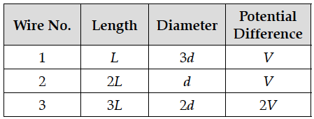
The following table gives the length of three copper wires, their diameters, and the applied potential difference across their ends. Arrange the wires in increasing order according to the following :
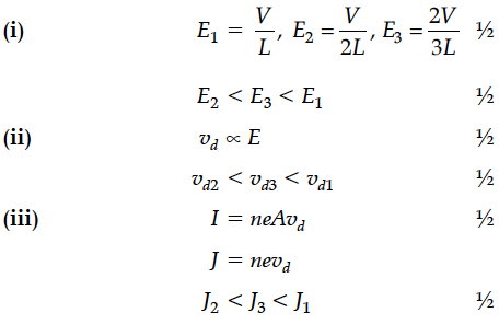
(i) The magnitude of the electric field within them,
(ii) The drift speed of electrons through them, and
(iii) The current density within them.

(i) The magnitude of the electric field within them,
(ii) The drift speed of electrons through them, and
(iii) The current density within them.


The plot of the variation of potential difference across a combination of three identical cells in series, versus current is shown below. What is the emf and internal resistance of each cell ?
Define relaxation time of the free electrons drifting in a conductor. How is it related to the drift velocity of free electrons ? Use this relation to deduce the expression for the electrical resistivity of the material.
Define the term current density of a metallic conductor. Deduce the relation connecting current density (J) and the conductivity σ of the conductor, when an electric field E, is applied to it.
A battery of emf 10 V and internal resistance 3 ohm is connected to a resistor. If the current in the circuit is 0.5 A, find :
(i) the resistance of the resistor;
(ii) the terminal voltage of the battery.
Draw a plot showing the variation of resistivity of a (i) conductor and (ii) semiconductor, with the increase in temperature. How does one explain this behaviour in terms of number density of charge carriers and the relaxation time ?
Two identical cells, each of emf E, having negligible internal resistance, are connected in parallel with each other across an external resistance R. What is the current through this resistance ?
The figure shows a plot of terminal voltage ‘V’ versus the current ‘i’ of a given cell. Calculate from the graph
(i) emf of the cell and (ii) internal resistance of the cell.
(i) Deduce the relation between current I flowing through a conductor and drift velocity of the electrons.
(ii) Figure shows a plot of current ‘I’ flowing through the cross-section of a wire versus the time ‘t’. Use the plot to find the charge flowing in 10 s through the wire.
(i) Three point charges q, – 4q and 2q are placed at the vertices of an equilateral triangle ABC of side ‘l’ as shown in the figure. Obtain the expression for the magnitude of the resultant electric force acting on the charge q.
(i) Write two properties by which electric potential is related to the electric field.
(ii) Two point charges q₁ and q₂ separated by a distance of r₁₂ are kept in an external electric field. Derive an expression for the potential energy of the system of two charges in the field.
A sinusoidal voltage of peak value 10 V is applied to a series LCR circuit in which resistance,capacitance and inductance have values of 10 Ω,1 µF and 1 H respectively. Find
(i) the peak voltage across the inductor at resonance
(ii) quality factor of the circuit.
A circuit containing an 80 mH inductor and a 250 µF capacitor in series connected to a 240 V,100 rad/s supply. The resistance of the circuit is negligible.
(i) Obtain rms value of current.
(ii) What is the total average power consumed by the circuit ?
(i) An electric dipole is kept first to the left and then to the right of a negatively charged infinite plane sheet having a uniform surface charge density. The arrows p₁ and p₂ show the directions of its electric dipole moments in the two cases.
Derive the expression for the average power dissipated in a series LCR circuit for an ac source of a voltage, V = sin ωt , carrying a current,i = sin (ωt + Φ)
Hence define the term “Wattless current”. State under what condition it can be realized in a circuit.
