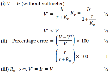
The potential difference across a resistor ‘r’ carrying current ‘I’ is Ir.
(i) Now if the potential difference across ‘r’ is measured using a voltmeter of resistance ‘’, show that the reading of voltmeter is less than the true value.
(ii) Find the percentage error in measuring the potential difference by a voltmeter.
(iii) At what value of ’, does the voltmeter measures the true potential difference?

A resistance of R Ω draws current from a potentiometer. The potentiometer has a total resistance \(R_0\) Ω as shown in the Fig below. A voltage V is supplied to the potentiometer. Derive an expression for the voltage across R when the sliding contact is in the middle of the potentiometer.
Derive the expression for the current density of a conductor in terms of the conductivity and applied electric field. Explain, with reason how the mobility of electrons in a conductor changes when the potential difference applied is doubled, keeping the temperature of the conductor constant.
The following table gives the length of three copper wires, their diameters, and the applied potential difference across their ends. Arrange the wires in increasing order according to the following :
(i) The magnitude of the electric field within them,
(ii) The drift speed of electrons through them, and
(iii) The current density within them.
A battery of emf 12 V and internal resistance 2 Ω is connected to a 4 Ω resistor as shown in the figure.
First a set of n equal resistors of R each is connected in series to a battery of emf E and internal resistance R. A current I is observed to flow. Then the n resistors are connected in parallel to the same battery. It is observed that the current becomes 10 times. What is n ?
Distinguish between emf (E) and terminal voltage (V) of a cell having internal resistance r. Draw a plot showing the variation of terminal voltage (V) Vs. the current (I) drawn from the cell. Using this plot, how does one determine the internal resistance of the cell ?
A cell of emf ‘E’ and internal resistance ‘r’ is connected across a variable load resistor R. Draw the plots of the terminal voltage V versus (i) R and
(ii) the current I.
It is found that when R = 4 Ω, the current is 1 A when R is increased to 9 Ω, the current reduces to 0.5 A. Find the values of the emf E and internal resistance r.
(i) Three point charges q, – 4q and 2q are placed at the vertices of an equilateral triangle ABC of side ‘l’ as shown in the figure. Obtain the expression for the magnitude of the resultant electric force acting on the charge q.
An electric dipole is placed in a uniform electric field.
(i) Show that no translatory force acts on it.
(ii) Derive an expression for the torque acting on it.
(iii) Find work done in rotating the dipole through 180°.
Define the term current density of a metallic conductor. Deduce the relation connecting current density (J) and the conductivity σ of the conductor, when an electric field E, is applied to it.
A charge is distributed uniformly over a ring of radius ‘a’. Obtain an expression for the electric intensity E at a point on the axis of the ring. Hence, show that for points at large distances from the ring, it behaves like a point charge.
The current, in the LCR circuit shown in the figure is observed to lead the voltage in phase. Without making any other change in the circuit, a capacitor,of capacitance C₀, is (appropriately) joined to the capacitor C. This results in making the current,in the ‘modified’ circuit, flow in phase with theapplied voltage.
Draw a diagram of the ‘modified’ circuit and obtain an expression for C₀ in terms of ω, L and C.
(i) The potential difference applied across a given resistor is altered so that the heat produced per second increases by a factor of 9. By what factor does the applied potential difference change ?
(ii) In the figure shown, an ammeter A and a resistor of 4 W are connected to the terminals of the source. The emf of the source is 12 V having an internal resistance of 2 W. Calculate the voltmeter and ammeter readings.
(a) Define the term ‘conductivity’ of a metallic wire. Write its SI unit.
(b) Using the concept of free electrons in a conductor, derive the expression for the conductivity of a wire in terms of number density and relaxation time. Hence obtain the relation between current density and the applied electric field E.
