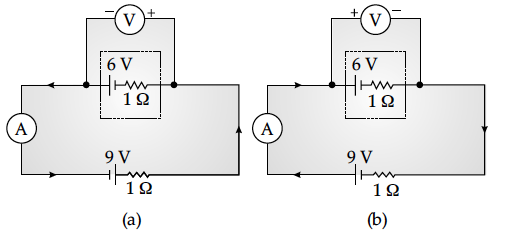
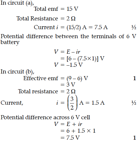
In the two electric circuits shown in the figure, determine the readings of ideal ammeter (A) and the ideal voltmeter (V).


In the circuit shown in the figure, find the total resistance of the circuit and the current in the arm CD.
Calculate the current drawn from the battery by the network of resistors shown in the figure.
How does one explain increase in resistivity of a metal with increase in temperature ?
(i) When an ac source is connected to an ideal capacitor show that the average power supplied by the source over a complete cycle is zero.
(ii) A lamp is connected in series with a capacitor.Predict your observation when the system is connected first across a dc and then an ac source.What happens in each case if the capacitance of the capacitor is reduced ?
(i) Derive an expression for drift velocity of free electrons.
(ii) How does drift velocity of electrons in a metallic conductor vary with increase in temperature ? Explain.
A source of ac voltage V = V₀ sin ωt is connected to a series combination of a resistor ‘R’ and a capacitor ‘C’. Draw the phasor diagram and use it to obtain the expression for
(i) impedance of the circuit and
(ii) phase angle.
(i) A point charge (+Q) is kept in the vicinity of an uncharged conducting plate. Sketch electric field lines between the charge and the plate.
(ii) Two infinitely large plane thin parallel sheets having surface charge densities σ₁ and σ₂ (σ₁ > σ₂) are shown in the figure. Write the magnitudes and directions of the fields in the regions marked II and III.
A charge + Q, is uniformly distributed within a sphere of radius R. Find the electric field, due to this charge distribution, at a distant point r from the centre of the sphere where :
(i) 0 < r < R
(ii) r > R
The following table gives the length of three copper wires, their diameters, and the applied potential difference across their ends. Arrange the wires in increasing order according to the following :
(i) The magnitude of the electric field within them,
(ii) The drift speed of electrons through them, and
(iii) The current density within them.
The potential difference across a resistor ‘r’ carrying current ‘I’ is Ir.
(i) Now if the potential difference across ‘r’ is measured using a voltmeter of resistance ‘’, show that the reading of voltmeter is less than the true value.
(ii) Find the percentage error in measuring the potential difference by a voltmeter.
(iii) At what value of ’, does the voltmeter measures the true potential difference?
