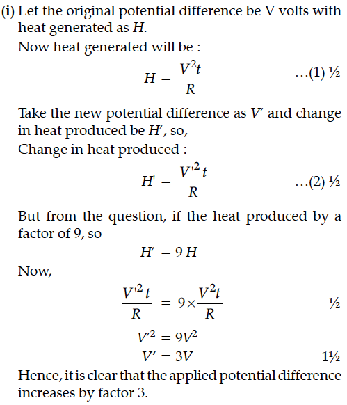
(i) The potential difference applied across a given resistor is altered so that the heat produced per second increases by a factor of 9. By what factor does the applied potential difference change ?
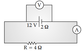
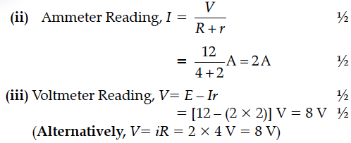
(ii) In the figure shown, an ammeter A and a resistor of 4 W are connected to the terminals of the source. The emf of the source is 12 V having an internal resistance of 2 W. Calculate the voltmeter and ammeter readings.

(ii) In the figure shown, an ammeter A and a resistor of 4 W are connected to the terminals of the source. The emf of the source is 12 V having an internal resistance of 2 W. Calculate the voltmeter and ammeter readings.


First a set of n equal resistors of R each is connected in series to a battery of emf E and internal resistance R. A current I is observed to flow. Then the n resistors are connected in parallel to the same battery. It is observed that the current becomes 10 times. What is n ?
The plot of the variation of potential difference across a combination of three identical cells in series, versus current is shown below. What is the emf and internal resistance of each cell ?
The following table gives the length of three copper wires, their diameters, and the applied potential difference across their ends. Arrange the wires in increasing order according to the following :
(i) The magnitude of the electric field within them,
(ii) The drift speed of electrons through them, and
(iii) The current density within them.
A battery of emf 12 V and internal resistance 2 Ω is connected to a 4 Ω resistor as shown in the figure.
Distinguish between emf (E) and terminal voltage (V) of a cell having internal resistance r. Draw a plot showing the variation of terminal voltage (V) Vs. the current (I) drawn from the cell. Using this plot, how does one determine the internal resistance of the cell ?
A battery of emf E and internal resistance, r, when connected with an external resistance of 12Ω produces a current of 0.5 A. When connected across a resistance of 25Ω, it produces a current of 0.25 A. Determine
(i) the emf and (ii) the internal resistance of the cell.
A student connects a cell, of emf E2 and internal resistance r2 with a cell of emf E1 and internal resistance r1, such that their combination has a net internal resistance less than r1. This combination is then connected across a resistance R. Draw a diagram of the 'set-up' and obtain an expression for the current flowing through the resistance.
Four point charges Q, q, Q and q are placed at the corners of a square of side ‘a’ as shown in the figure.
Two material bars A and B of equal area of crosssection, are connected in series to a DC supply. A is made of usual resistance wire and B of an n-type semiconductor.
(i) In which bar is drift speed of free electrons greater?
(ii) If the same constant current continues to flow for a long time, how will the voltage drop across A and B be affected?
Justify each error.
The figure shows a series LCR circuit with L = 5.0 H, C = 80 µF, R = 40 Ω connected to a variable frequency of 240 V source. Calculate
First a set of n equal resistors of R each is connected in series to a battery of emf E and internal resistance R. A current I is observed to flow. Then the n resistors are connected in parallel to the same battery. It is observed that the current becomes 10 times. What is n ?
A sinusoidal voltage of peak value 10 V is applied to a series LCR circuit in which resistance,capacitance and inductance have values of 10 Ω,1 µF and 1 H respectively. Find
(i) the peak voltage across the inductor at resonance
(ii) quality factor of the circuit.
A circuit containing an 80 mH inductor and a 250 µF capacitor in series connected to a 240 V,100 rad/s supply. The resistance of the circuit is negligible.
(i) Obtain rms value of current.
(ii) What is the total average power consumed by the circuit ?
Derive an expression for electric field of a dipole at a point on the equatorial plane of the dipole. How does the field vary at large distances?
