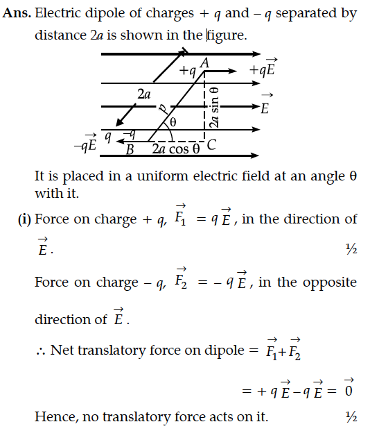
An electric dipole is placed in a uniform electric field.
(i) Show that no translatory force acts on it.
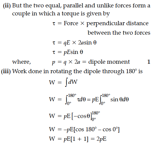
(ii) Derive an expression for the torque acting on it.
(iii) Find work done in rotating the dipole through 180°.
(i) Show that no translatory force acts on it.
(ii) Derive an expression for the torque acting on it.
(iii) Find work done in rotating the dipole through 180°.


An electric dipole is held in a uniform electric field.
(i) Show that the net force acting on it is zero.
(ii) The dipole is aligned parallel to the field. Find the work done in rotating it through the angle of 180°.
(i) Derive the expression for electric field at a point on the equatorial line of an electric dipole.
(ii) Depict the orientation of the dipole in (i) stable, (ii) unstable equilibrium in a uniform electric field.
Derive an expression for electric field of a dipole at a point on the equatorial plane of the dipole. How does the field vary at large distances?
In the figure the net electric flux through the area... when the system is in air. On immersing the system in water,the net electric flux through the area
Find the expression for electric field intensity in an axial position due to electric dipole.
A point charge +Q is placed in the vicinity of a conducting surface. Draw the electric field lines between the surface and the charge.
An electric dipole of length 4 cm, when placed with its axis making an angle of 60° with a uniform electric field, experiences a torque of Nm. Calculate the potential energy of the dipole, if it has charge ± 8 nC.
(i) Derive the expression for electric field at a point on the equatorial line of an electric dipole.
(ii) Depict the orientation of the dipole in (i) stable, (ii) unstable equilibrium in a uniform electric field.
Derive the expression for the current density of a conductor in terms of the conductivity and applied electric field. Explain, with reason how the mobility of electrons in a conductor changes when the potential difference applied is doubled, keeping the temperature of the conductor constant.
A source of ac voltage V = V₀ sin ωt is connected to a series combination of a resistor ‘R’ and a capacitor ‘C’. Draw the phasor diagram and use it to obtain the expression for
(i) impedance of the circuit and
(ii) phase angle.
The figure shows a series LCR circuit with L = 5.0 H, C = 80 µF, R = 40 Ω connected to a variable frequency of 240 V source. Calculate
(i) When an ac source is connected to an ideal inductor shows that the average power supplied by the source over a complete cycle is zero.
(ii) A lamp is connected in series with an inductor and an ac source. What happens to the brightness of the lamp when the key is plugged in and an iron rod is inserted inside the inductor ? Explain.
A source of ac voltage V = V₀ sin ωt, is connected across a pure inductor of inductance L. Derive the expressions for the instantaneous current in the circuit. Show that average power dissipated in the circuit is zero.
The temperature coefficient of resistivity, for two materials A and B, are 0.0031 / °C and 0.0068 / °C respectively.
Two resistors R1 and R2, made from materials A and B, respectively, have resistances of 200 Ω and 100 Ω at 0°C. Show on a diagram, the 'colour code', of a carbon resistor, that would have a resistance
equal to the series combination of R1 and R2, at a temperature of 100°C.
(Neglect the ring corresponding to the tolerance of the carbon resistor).
