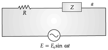
An alternating voltage E = E₀ sin ωt is applied to the circuit containing a resistor R connected in series with a black box. The current in the circuit is found to be I=I₀ (sin ωt+π/4)

(i) State whether the element in the black box is a capacitor or inductor.
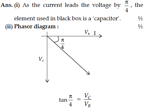
(ii) Draw the corresponding phasor diagram and find the impedance in terms of R.

(i) State whether the element in the black box is a capacitor or inductor.
(ii) Draw the corresponding phasor diagram and find the impedance in terms of R.


An ac voltage V = V₀ sin ωt is applied to a pure inductor L. Obtain an expression for the current in the circuit. Prove that the average power supplied to an inductor over one complete cycle is zero.
A source of ac voltage V = V₀ sin ωt, is connected across a pure inductor of inductance L. Derive the expressions for the instantaneous current in the circuit. Show that average power dissipated in the circuit is zero.
A voltage V = V₀ sin ωt is applied to a series LCR circuit. Derive the expression for the average power dissipate over a cycle.Under what conditions is
(i) no power dissipated even though the current flows through the circuit,
(ii)maximum power dissipated in the circuit ?
An alternating voltage given by V = 140sin314 t is connected across a pure resistor of 50 Find :
(i) the frequency of the source.
(ii) the rms current through the resistor.
A source of ac voltage V = V₀ sin ωt is connected to a series combination of a resistor ‘R’ and a capacitor ‘C’. Draw the phasor diagram and use it to obtain the expression for
(i) impedance of the circuit and
(ii) phase angle.
A small signal voltage V(t) = V₀ sin(ωt) is applied across an ideal capacitor C
(a) Current I(t) is in phase with voltage V(t).
(b) Current I(t) leads voltage V(t) by 180°.
(c) Current I(t), lags voltage V(t) by 90°.
(d) Over a full cycle the capacitor C does not consume any energy from the voltage source
A sinusoidal voltage of peak value 10 V is applied to a series LCR circuit in which resistance,capacitance and inductance have values of 10 Ω,1 µF and 1 H respectively. Find
(i) the peak voltage across the inductor at resonance
(ii) quality factor of the circuit.
Two electric bulbs P and Q have their resistances in the ratio of 1 : 2. They are connected in series across a battery. Find the ratio of the power dissipation in these bulbs.
Two point charges q1 and q2 are located at and respectively in an external electric field E. Obtain the expression for the total work done in assembling this configuration.
Two metallic wires P₁ and P₂ of the same material and same length but different cross-sectional areas A₁ and A₂ are joined together and then connected to a source of emf. Find the ratio of the drift velocities of free electrons in the wires P₁ and P₂ if the wires are connected
(i) in series, and (ii) in parallel.
The figure shows a plot of terminal voltage ‘V’ versus the current ‘i’ of a given cell. Calculate from the graph
(i) emf of the cell and (ii) internal resistance of the cell.
Distinguish between emf (E) and terminal voltage (V) of a cell having internal resistance r. Draw a plot showing the variation of terminal voltage (V) Vs. the current (I) drawn from the cell. Using this plot, how does one determine the internal resistance of the cell ?
Two closely spaced equipotential surfaces A and B with potentials V and V + , (where is the change in V), are kept distance apart as shown in the figure. Deduce the relation between the electric field and the potential gradient between them. Write the two important conclusions concerning the relation between the electric field and electric potentials.
N spherical droplets, each of radius r, have been charged to have a potential V each. If all these droplets were to coalesce to form a single large drop, what would be the potential of this large drop ?
(It is given that the capacitance of a sphere of radius x equals
