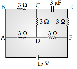
In the circuit shown in the figure, find the total resistance of the circuit and the current in the arm CD.


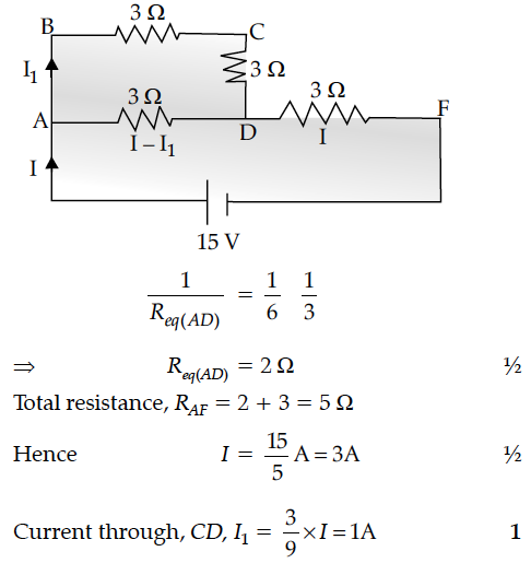
In a steady state when capacitor is fully charged no current flows through branch CEF and the given circuit reduced to


In the two electric circuits shown in the figure, determine the readings of ideal ammeter (A) and the ideal voltmeter (V).
Calculate the current drawn from the battery by the network of resistors shown in the figure.
How does one explain increase in resistivity of a metal with increase in temperature ?
Plot a graph showing the variation of current I versus resistance R, connected to a cell of emf E and internal resistance r.
Find the expression for electric field intensity in an axial position due to electric dipole.
Two cells of emfs 1.5 V and 2.0 V having internal resistances 0.2Ω and 0.3Ω respectively are connected in parallel. Calculate the emf and internal resistance of the equivalent cell.
A test charge q is moved without acceleration from A to C along the path from A to B and then from B to C in electric field E as shown in the figure.
An electric dipole is placed in a uniform electric field with its dipole moment parallel to the field. Find
(i) the work done in turning the dipole till its dipole moment points in the direction opposite to .
(ii) the orientation of the dipole for which the torque acting on it becomes maximum.
Draw a plot showing the variation of resistivity of a (i) conductor and (ii) semiconductor, with the increase in temperature. How does one explain this behaviour in terms of number density of charge carriers and the relaxation time ?
In a series LCR circuit, obtain the conditions under which
(i) the impedance of the circuit is minimum, and
(ii) wattless current flows in the circuit.
A battery of emf 10 V and internal resistance 3 ohm is connected to a resistor. If the current in the circuit is 0.5 A, find :
(i) the resistance of the resistor;
(ii) the terminal voltage of the battery.
