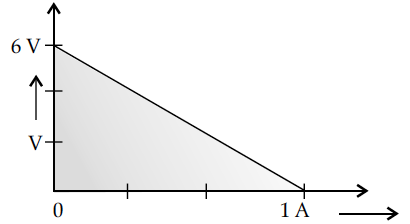
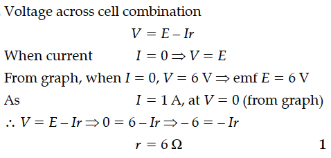
The plot of the variation of potential difference across a combination of three identical cells in series, versus current is shown below. What is the emf and internal resistance of each cell ?


Plot a graph showing the variation of current I versus resistance R, connected to a cell of emf E and internal resistance r.
The figure shows a plot of terminal voltage ‘V’ versus the current ‘i’ of a given cell. Calculate from the graph
(i) emf of the cell and (ii) internal resistance of the cell.
Two cells of emfs 1.5 V and 2.0 V having internal resistances 0.2Ω and 0.3Ω respectively are connected in parallel. Calculate the emf and internal resistance of the equivalent cell.
A 9 V battery is connected in series with a resistor. The terminal voltage is found to be 8 V. Current through the circuit is measured as 5 A. What is the internal resistance of the battery?
Write the expression for the drift velocity of charge carriers in a conductor of length l across which a potential difference V is applied.
Draw a graph to show the variation of resistance of a metal wire as a function of its diameter keeping its length and material constant.
A network of resistors is connected to a 16 V battery with internal resistance of 1 Ω, as shown in the following figure. Compute the equivalent resistance of the network.
A point charge Q is placed at point ‘O’ as shown in figure. Is the potential at point A, i.e., , greater, smaller or equal to potential, at point B, when Q is (i) positive, and (ii) negative charge?
Why are electric field lines perpendicular at a point on an equipotential surface of a conductor ?
In the given figure, charge +Q is placed at the centre of a dotted circle. Work done in taking another charge +q from A to B is W₁ and from B to C is W₂. Which one of the following is correct ?
i) W₁ > W₂
(ii) W₁ = W₂
(iii) W₁ < W₂
Why is choke coil needed in the use of fluorescent tubes with ac mains ?
In a series LR circuit = R and power factor of the circuit is P₁. When capacitor with capacitance C such that = is put in series, the power factor becomes P₂. Calculate P₁ / P₂.
Why should electrostatic field be zero inside a conductor ?
Figure shows a point charge + Q, located at a distance R/2 from the centre of a spherical metal shell. Draw the electric field lines for the given system.
