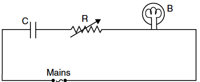
A capacitor ‘C’, a variable resistor ‘R’ and a bulb ‘B’ are connected in series to the ac mains in circuit as shown. The bulb glows with some brightness.How will the glow of the bulb change if
(i) a dielectric slab is introduced between the plates of the capacitor, keeping resistance R to be the same;
(ii) the resistance R is increased keeping the same capacitance ?

(i) a dielectric slab is introduced between the plates of the capacitor, keeping resistance R to be the same;
(ii) the resistance R is increased keeping the same capacitance ?

(i) When a dielectric slab is introduced in between the plates of capacitor, its capacitance will increase which tends to decrease the potential drop across the capacitor, i.e., V = Q/C. As a result of this,potential drop across bulb will increase as they are connected in series, so the brightness of the bulb will increase.
(ii) As the resistance R increases, potential drop across the resistor will also increase which lead to decrease in potential drop across the bulb, since it is connected in series. Hence, the brightness of the bulb will decrease.
(ii) As the resistance R increases, potential drop across the resistor will also increase which lead to decrease in potential drop across the bulb, since it is connected in series. Hence, the brightness of the bulb will decrease.
An inductor of 200 mH, capacitor of 400 µF and a resistor of 10 Ω are connected in series to ac source of 50 V of variable frequency. Calculate the
(a) angular frequency at which maximum power dissipation occurs in the circuit and the corresponding value of the effective current, and
(b) value of Q-factor in the circuit.
The figure shows a series LCR circuit connected to a variable frequency of 200 V source with L = 50 mH, C = 80 µF and R = 40 Ω find.
(i) the source frequency which drives the circuit in resonance;
(ii) the quality factor (Q) of the circuit.
A source of ac voltage V = V₀ sin ωt is connected to a series combination of a resistor ‘R’ and a capacitor ‘C’. Draw the phasor diagram and use it to obtain the expression for
(i) impedance of the circuit and
(ii) phase angle.
A voltage V = V₀ sin ωt is applied to a series LCR circuit. Derive the expression for the average power dissipate over a cycle.Under what conditions is
(i) no power dissipated even though the current flows through the circuit,
(ii)maximum power dissipated in the circuit ?
A circuit containing an 80 mH inductor and a 250 µF capacitor in series connected to a 240 V,100 rad/s supply. The resistance of the circuit is negligible.
(i) Obtain rms value of current.
(ii) What is the total average power consumed by the circuit ?
In the following circuit, calculate (i) the capacitance of the capacitor, if the power factor of the circuit is unity, (ii) the Q-factor of this circuit. What is the significance of the Q-factor in ac circuit ? Given the angular frequency of the ac source to be 100rad/s. Calculate the average power dissipated in the circuit.
An AC voltage source of variable angular frequency ω and fixed amplitude V connected in series with a capacitance C and an electric bulb of resistance R (inductance zero). When ω is increased
(a) The bulb glows dimmer
(b) The bulb glows brighter
(c) Net impedance of circuit is unchanged
(d) Total impedance of the circuit increases
Show that the current leads the voltage in phase by in an ac circuit containing an ideal capacitor.
Distinguish between emf (E) and terminal voltage (V) of a cell having internal resistance r. Draw a plot showing the variation of terminal voltage (V) Vs. the current (I) drawn from the cell. Using this plot, how does one determine the internal resistance of the cell ?
A battery of emf 10 V and internal resistance 3 ohm is connected to a resistor. If the current in the circuit is 0.5 A, find :
(i) the resistance of the resistor;
(ii) the terminal voltage of the battery.
Two cells of E.M.F. 10 V and 2 V and internal resistances 10 Ω and 5 Ω respectively, are connected in parallel as shown. Find the effective voltage across R.
A particle of mass 10⁻³ kg and charge 5 mC enters into a uniform electric field of 2×10⁵ NC⁻¹, moving with a velocity of 20 ms⁻¹ in a direction opposite to that of the field. Calculate the distance it would travel before coming to rest.
Find the P.E. associated with a charge q if it were present at the point P with respect to the ‘setup’ of two charged spheres, arranged as shown. Here O is the mid-point of the line O1O2.
A battery of emf E and internal resistance, r, when connected with an external resistance of 12Ω produces a current of 0.5 A. When connected across a resistance of 25Ω, it produces a current of 0.25 A. Determine
(i) the emf and (ii) the internal resistance of the cell.
