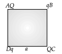
Four point charges Q, q, Q and q are placed at the corners of a square of side ‘a’ as shown in the figure.

Find the
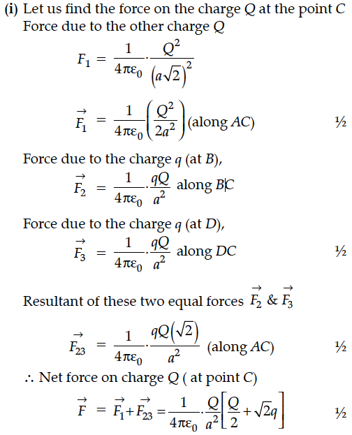
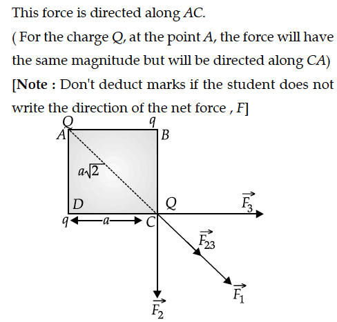
(i) resultant electric force on a charge Q, and
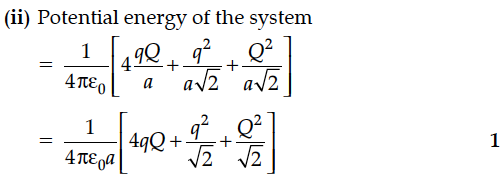
(ii) potential energy of this system.

Find the
(i) resultant electric force on a charge Q, and
(ii) potential energy of this system.


Four point charges –Q,-q,2q,2Q are placed at different corners of a square . The relation between Q and q for which the potential at the center of the square is zero
1.Q=q
2.Q=1/q
3.Q=-q
4. Q=-1/q
Two point charges q and –2q are kept d distance apart. Find the location of the point relative to charge q at which potential due to this system of charges is zero.
A point charge +Q is placed at point O as shown in the figure. Is the potential difference – positive, negative or zero ?
For any charge configuration, equipotential surface through a point is normal to the electric field. Justify.
Figure shows the field lines due to a positive charge. Is the work done by the field in moving a small positive charge from Q to P, positive or negative? Give reason.
What is the amount of work done in moving a point charge around a circular arc of radius r at the center where another point charge is located ?
The capacitance of a capacitor will decrease if we introduce a slab of:
(a) copper
(b) aluminium
(c) zinc
(d) None of these
(i) Deduce the relation between current I flowing through a conductor and drift velocity of the electrons.
(ii) Figure shows a plot of current ‘I’ flowing through the cross-section of a wire versus the time ‘t’. Use the plot to find the charge flowing in 10 s through the wire.
The temperature coefficient of resistivity, for two materials A and B, are 0.0031 / °C and 0.0068 / °C respectively.
Two resistors R1 and R2, made from materials A and B, respectively, have resistances of 200 Ω and 100 Ω at 0°C. Show on a diagram, the 'colour code', of a carbon resistor, that would have a resistance
equal to the series combination of R1 and R2, at a temperature of 100°C.
(Neglect the ring corresponding to the tolerance of the carbon resistor).
A source of ac voltage V = V₀ sin ωt is connected to a series combination of a resistor ‘R’ and a capacitor ‘C’. Draw the phasor diagram and use it to obtain the expression for
(i) impedance of the circuit and
(ii) phase angle.
First a set of n equal resistors of R each is connected in series to a battery of emf E and internal resistance R. A current I is observed to flow. Then the n resistors are connected in parallel to the same battery. It is observed that the current becomes 10 times. What is n ?
The potential difference across a resistor ‘r’ carrying current ‘I’ is Ir.
(i) Now if the potential difference across ‘r’ is measured using a voltmeter of resistance ‘’, show that the reading of voltmeter is less than the true value.
(ii) Find the percentage error in measuring the potential difference by a voltmeter.
(iii) At what value of ’, does the voltmeter measures the true potential difference?
Two cells of emfs E₁ & E₂ and internal resistances r₁ & r₂ respectively are connected in parallel. Obtain expressions for the equivalent.
(i) resistance and
(ii) emf of the combination
The following table gives the length of three copper wires, their diameters, and the applied potential difference across their ends. Arrange the wires in increasing order according to the following :
(i) The magnitude of the electric field within them,
(ii) The drift speed of electrons through them, and
(iii) The current density within them.
