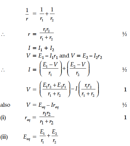
Two cells of emfs E₁ & E₂ and internal resistances r₁ & r₂ respectively are connected in parallel. Obtain expressions for the equivalent.
(i) resistance and
(ii) emf of the combination
(i) resistance and
(ii) emf of the combination


Two cells of emfs 1.5 V and 2.0 V having internal resistances 0.2Ω and 0.3Ω respectively are connected in parallel. Calculate the emf and internal resistance of the equivalent cell.
Two cells of E.M.F. 10 V and 2 V and internal resistances 10 Ω and 5 Ω respectively, are connected in parallel as shown. Find the effective voltage across R.
Two cells of emf and have internal resistance and . Deduce an expression for equivalent emf of their parallel combination.
A cell of emf 4 V and internal resistance 1 W is connected to a d.c. source of 10 V through a resistor of 5 W. Calculate the terminal voltage across the cell during charging.
Two electric bulbs P and Q have their resistances in the ratio of 1 : 2. They are connected in series across a battery. Find the ratio of the power dissipation in these bulbs.
Two identical cells, each of emf E, having negligible internal resistance, are connected in parallel with each other across an external resistance R. What is the current through this resistance ?
A network of resistors is connected to a 16 V battery with internal resistance of 1 Ω, as shown in the following figure. Compute the equivalent resistance of the network.
An inductor L of inductance is connected in series with a bulb B and an ac source. How would brightness of the bulb change when
(i) number of turns in the inductor is reduced,
(ii) an iron rod is inserted in the inductor and
(iii) a capacitor of reactance is inserted in series in the circuit. Justify your answer in each case.
(i) An electric dipole is kept first to the left and then to the right of a negatively charged infinite plane sheet having a uniform surface charge density. The arrows p₁ and p₂ show the directions of its electric dipole moments in the two cases.
A sinusoidal voltage of peak value 10 V is applied to a series LCR circuit in which resistance,capacitance and inductance have values of 10 Ω,1 µF and 1 H respectively. Find
(i) the peak voltage across the inductor at resonance
(ii) quality factor of the circuit.
(i) Three point charges q, – 4q and 2q are placed at the vertices of an equilateral triangle ABC of side ‘l’ as shown in the figure. Obtain the expression for the magnitude of the resultant electric force acting on the charge q.
The potential difference across a resistor ‘r’ carrying current ‘I’ is Ir.
(i) Now if the potential difference across ‘r’ is measured using a voltmeter of resistance ‘’, show that the reading of voltmeter is less than the true value.
(ii) Find the percentage error in measuring the potential difference by a voltmeter.
(iii) At what value of ’, does the voltmeter measures the true potential difference?
The current, in the LCR circuit shown in the figure is observed to lead the voltage in phase. Without making any other change in the circuit, a capacitor,of capacitance C₀, is (appropriately) joined to the capacitor C. This results in making the current,in the ‘modified’ circuit, flow in phase with theapplied voltage.
Draw a diagram of the ‘modified’ circuit and obtain an expression for C₀ in terms of ω, L and C.
A source of ac voltage V = V₀ sin ωt is connected to a series combination of a resistor ‘R’ and a capacitor ‘C’. Draw the phasor diagram and use it to obtain the expression for
(i) impedance of the circuit and
(ii) phase angle.
